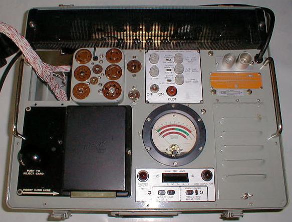
The is the USM-118B. The USM-118A looks identical, and the main
difference between the two is a different type of meter
protection. Either are quite good units as long as the physical
condition is good (no corrosion, good transformers, etc.) The
Western Electric KS-15874 looks a little different and has a larger
meter, but is the same electrically.
In the lower left there is an arrow pointing to where the punched cards
slide in. We don't use those cards with the computerized version,
of course (but you could if the card reader is functional, even after
the tester has had the computer wiring harness installed). There
is a hinged cover on the right that houses more controls, which is
explained below.
This particular tester has the computer wiring harness installed.
Notice it is simply a neat, unobtrusive bundle of wires terminating in
two circular connectors. It exits the tester in an area that
normally contains a small metal box meant to hold test cards.
This harness does not interfere with the operation of the tester in any
way.
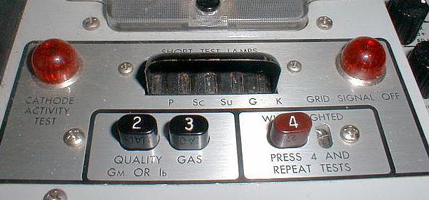
Here is a close up of the test buttons and short indicators.
After inserting a tube and calling up the proper test on the computer,
normally you simply check to make sure no short lamps are lit, press
button "2", and read the meter. A chart on the computer screen
converts the meter reading for you and tells whether the tube passes
the quality test. Then you press button "3" and read the meter to
check for gas and/or grid emission. If the tube is a dual triode
like a 12AX7, a lamp to the right of button "4" lights, telling you to
repeat tests "2" and "3" while holding down button "4". The
"Cathode Activity Test" and "Grid Signal Off" lamps are explained below.
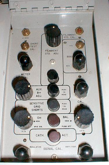
Here are the controls under the hinged cover. The majority of
these controls are calibration controls, and their functions are
covered in the calibration routines embedded in the software. The
only controls here you might access regularly are the "Gm BAL", "GRID
SIG. OFF", "SENSITIVE GRID SHORTS", and "CATH. ACT.". The
first two are used together, and should be used to ensure the highest
accuracy, especially when testing directly heated tubes. When you
press the "GRID SIG. OFF" button, the "Grid Signal Off" lamp
illuminates and the .222 volt AC signal is removed from the grid.
In this condition the meter should read exactly zero when you press
test button "2". You can use the "Gm BAL" controls to set it to
zero. This achieves a perfect balance of the Gm bridge circuit,
creating the most accurate reading possible once the "Grid Sig. Off"
button is returned to normal.
The "SENSITIVE GRID SHORTS" button us used to check for very small
amounts of leakage to other tube elements. It is always a good
idea to use this test when testing audio tubes, or other tubes used in
a critical application. If there is any grid leakage of 10
megohms or less the grid shorts lamp will begin to flicker.
The "CATH. ACT." is the life test. Pressing it illuminates the
proper indicator to let you know this test is active, and reduces the
heater voltage by 10%. While holding down test button "2", you
can watch the meter reaction to determine how much the tube reacts to
this reduction in heater voltage. Little reaction means the tube
likely has seen little use, a lot of reaction means the tube likely has
seen a lot of use.
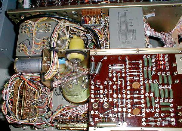
Here is the inside of a USM-118B. This one has the computer
wiring harness installed, and unless you look closely you would
probably not even notice it. If you are wondering what the big
light bulb in the middle is for, it is the overload protector for the
filament transformer.
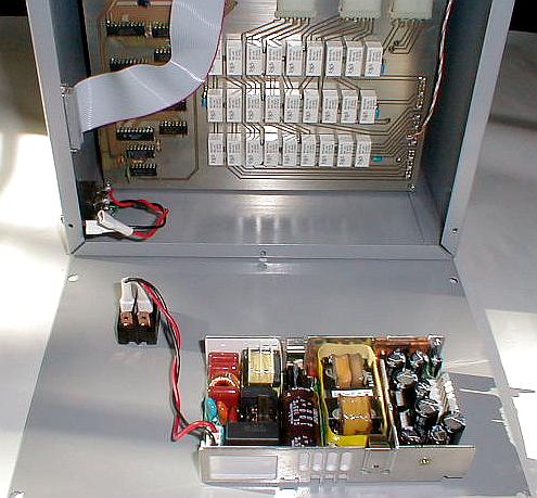
Here is the control box with the back cover removed. In the
foreground is the power supply and power switch. On the left you
can see the AC power inlet and a standard DB-25 computer
connector. The circuit board visible inside is the Adapter
Board. This board uses 27 relays which are only used when
one of the tube sockets on the control box itself is used. The
control box is securely grounded at the AC inlet.
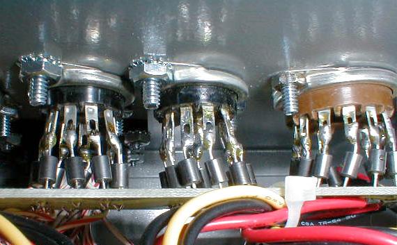
This is a close up of how the tube sockets on the control box are
wired. Notice ferrite beads are used on each lead to help prevent
any unwanted oscillations. The circuit board these beads connect
to is called the Socket Board, and connects to the Adapter Board shown
in the previous picture.
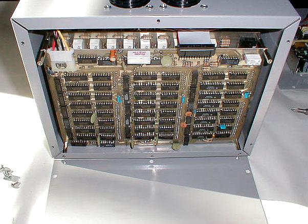
Another picture of the inside of the control box, this time with the
front cover removed. Here you can see the Control Board,
which contains the control and protection circuitry for all the the
relays except for the ones on the Adapter Board. Discreet logic
chips are used in order to ensure future parts availability and ease of
troubleshooting. This board contains no less than 10 separate
circuits dedicated solely to relay protection, and extensive measures
have been employed to maximize noise immunity. Also visible
is the top row of relays on Relay Board 3. It holds 61 relays,
and connects to the Control Board via 2 ribbon cables. There are
2 more similar boards, Relay Board 2 and Relay Board 1, which are not
visible. These boards also contain 61 relays each. Home